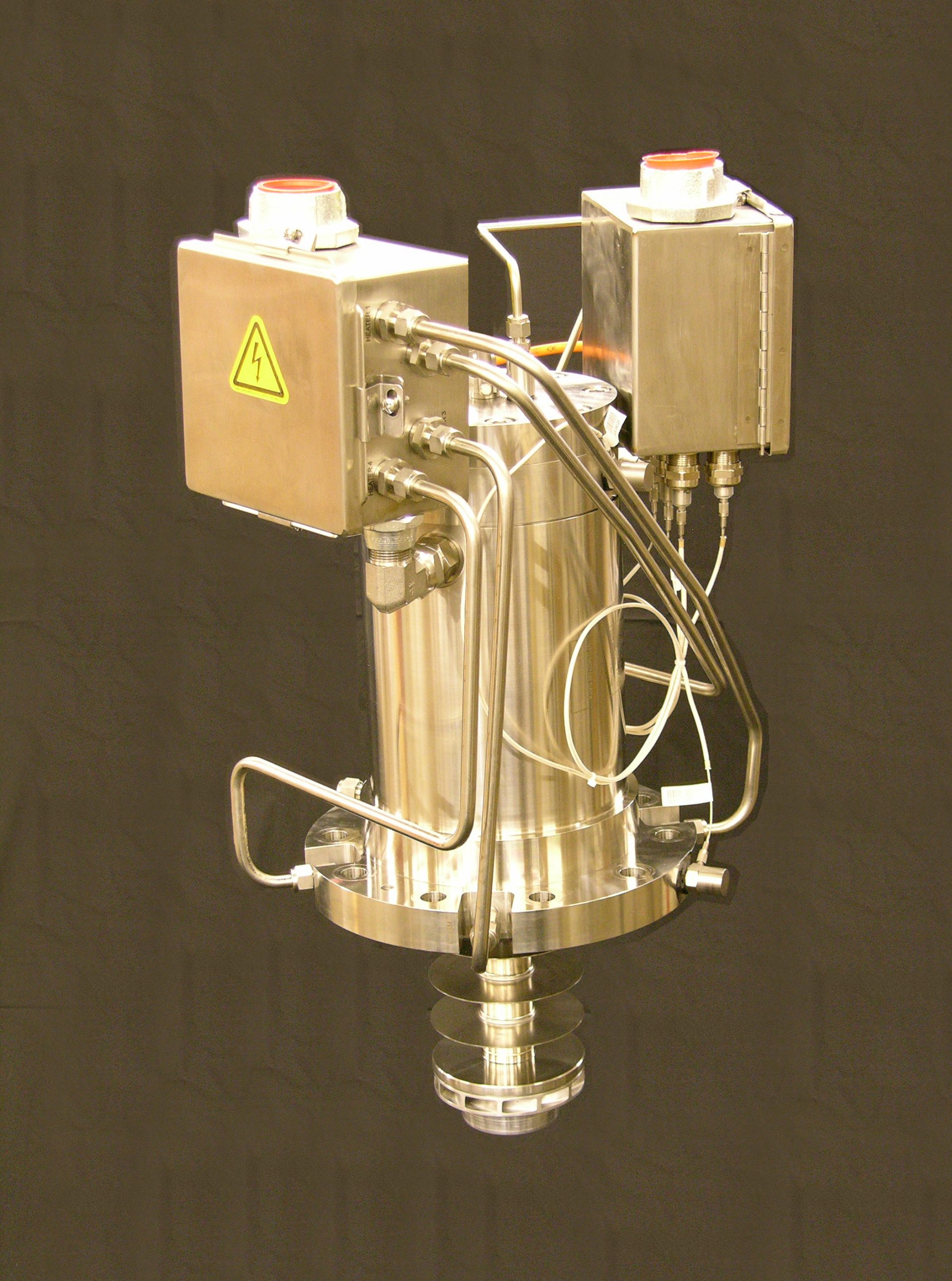

- #Helium electric generator generator#
- #Helium electric generator full#
- #Helium electric generator free#
For the same size of ceramic, low frequency vibrational environments will require devices designed to apply higher stresses than high frequency vibrational environments. The lines are “contours of constant electrical power output” showing the trade-off between applied strain and applied frequency for this small sample of ceramic. The Y axis of this graph shows the applied +/- uniform strain, the X axis shows the frequency of sinusoidal strain application. It is far easier experimentally to measure surface strain on various constructions and infer the interior stresses than to measure stress directly.This figure is a commonly used as a rule of thumb arising from the tensile limit of the materials and is incorporated into the graph as an upper limit. Piezoceramics' mechanical dynamic excitation limits can be easily approximated as +/-500E-06 meters/meter (i.e.

Strain rather than stress is utilized as the independent applied mechanical input for two reasons: 025mm edge over a range of frequenciesĮlectrical output: taken between the two electrodes with imaginary perfect circuitry Polarization: Through the 0.25mm thickness
#Helium electric generator full#
Standard mounting techniques for bending generatorsĮlectrodes: full coverage of both 10mm x 10mm faces In practice no material is perfectly rigid, so typically the designers are left to puzzle out why the actuator is only making 1/10 the expected excursion. In theory if the end clamps are perfectly rigid the motion at the center of the beam will be exactly zero. by bonding to the edges of a cutout or clamping as illustrated in Figure 26). Ridgid clamping at both ends is often considered by novice designers for expedience (e.g. 55L apart, where L is the length of the beam. For high frequency-resonant applications, power dissipation at the mounts can be minimized by using nodal mounts. Compared to the cantilever mount, the simple beam mount provides increased stiffness and frequency.

The simple beam mount allows the ends to move in and out as well as rotate but fixes their vertical position. The second category, known as the simple beam mount, has power input at the center and is mounted at the ends. Known as the cantilever mount, it provides maximum compliance. The first category has power input at one end and is mounted at the other. Standard mounts for bending generators are illustrated in Figure 26 and fall into two general categories.
#Helium electric generator generator#
The voltage versus charge diagram for a piezoelectric generator element. This occurs when the charge equals one half the short-circuit charge. Work is maximized when the charge moved permits one half the open circuit voltage to be developed. Generally, a piezo generator must move a specified amount of charge and supply a specified voltage, which determines its operating point on the voltage vs. All other values of simultaneous charge and voltage levels are determined by a line drawn between these points on a voltage versus charge line, as shown in Figure 13.

Charge is at a maximum when the voltage is zero, and voltage is at a maximum when the charge transfer is zero. Open-circuit voltage, Vo, refers to the voltage developed, at the maximum recommended stress level, when charge is prohibited from traveling from one electrode to the other.
#Helium electric generator free#
Short-circuit charge, Qs, refers to the total charge developed, at the maximum recommended stress level, when the charge is completely free to travel from one electrode to the other, and is not asked to build up any voltage. Piezoelectric generators are usually specified in terms of their short-circuit charge and open-circuit voltage.


 0 kommentar(er)
